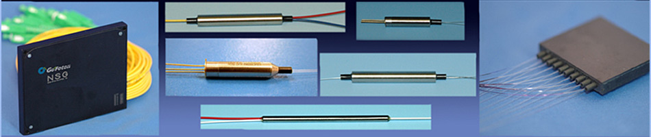
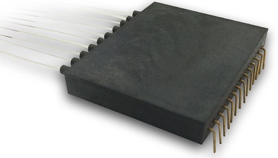
Integrated Tap Detector Array, 4, 8 and 10 Channels
 Applications: Applications:
-
EDFA Power Monitoring/Control
-
DWDM Channel Monitoring
-
ROADM Port Monitoring/Control
Features:
-
Low Insertion Loss
-
Low Wavelength Dependent Loss
-
Low Dark Current
-
Telcordia GR-468-CORE Compliant
-
Broad Wavelength Range
-
Excellent Thermal Stability
Description:
Go!Foton’s Integrated Tap Detector Array combines optical couplers, based on our filter-on-lens technology, with Go!Foton’s proprietary PIN photodiodes to create a multi channel optical power monitor. The integrated design reduces the number of parts, minimizes fiber handling and results in a compact footprint, which simplifies assembly of amplifier and WDM monitoring devices. The hermetically sealed InGaAs photo detector has a low dark current, a flat and rapid power response and extremely high temperature stability across a wide wavelength range. This device is also available with “Ribbonized Fiber” option for easy connection.
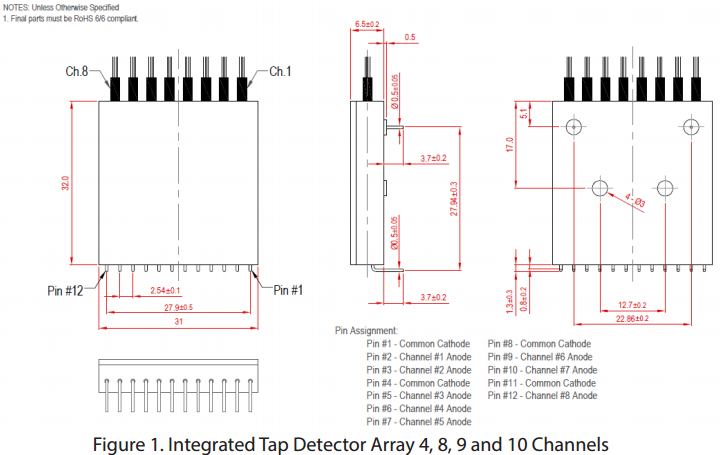
Dimensions:
Specifications:
| A. Absolute Maximum Rating |
|
|
|
|
|
|
|
|
|
|
|
|
|
|
| Parameters |
Symbol |
Unit |
Specification |
| Min |
Typ |
Max |
| Operating Temperature |
Top |
°C |
-40 |
- |
+85 |
| Operating humidity Range (No Condensation) |
RHOP |
% |
5 |
- |
95 |
| Storage Temperature Range |
Tstg |
°C |
-40 |
- |
+85 |
| Storage Humidity Range (No Condensation) |
RHstg |
% |
5 |
- |
95 |
| Reverse Bias |
Vr |
V |
- |
- |
25 |
| Forward Current |
If |
mA |
- |
- |
10 |
| Electrostatic Discharge(ESD) Threshold C:100pF,R:1.5kΩ,Human Body Model |
VESD |
V |
500 |
- |
- |
| Soldering Temperature (< 10 sec) atleast 2mm away from the device’s body. |
TSol |
°C |
- |
250 |
- |
| B. Optical & Electrical Characteristics |
|
|
|
|
|
|
|
|
|
|
|
|
|
| Parameter |
Symbol |
Unit |
Specification |
Condition |
| Tap Ratio |
TR |
% |
0.5 |
1 |
2 |
5 |
10 |
30 |
50 |
|
| Wavelength Range |
λR |
nm |
1520~1570 |
C-Band |
| 1570~1610 |
L-Band |
| 1510~1610 |
CL-Band |
| Insertion Loss |
IL |
dB |
<0.5 |
<0.5 |
<0.5 |
<0.6 |
<0.8 |
<2.3 |
<3.6 |
λR , Top |
| Wavelength Flatness |
WDL |
dB |
<0.1 |
C-Band and L-Band |
| <0.15 |
CL-Band |
| Temperature Dependent Loss |
TDL |
dB |
<0.15 |
1550nm , Top |
| Polarization Dependent Loss |
PDL |
dB |
<0.05 |
1550nm,RT |
| Return Loss |
RL |
dB |
>50 |
1550nm,RT |
| Minimum Responsivity |
RsMIN |
mA/W |
4 |
8 |
16 |
45 |
70 |
240 |
350 |
λR , Top, Vr:5V |
| Maximum Responsivity |
RsMAX |
mA/W |
8.5 |
15 |
26 |
65 |
145 |
400 |
600 |
λR , Top, Vr:5V |
| Wavelength Dependent Responsivity |
WDRs |
dB |
<0.4 |
C-Band , Top, Vr:5V |
| <0.4 |
L-Band , Top, Vr:5V |
| <0.45 |
CL-Band , Top, Vr:5V |
| Temperature Dependent Responsivity |
TDRs |
dB |
<0.4 |
C-Band , Top, Vr:5V |
| <0.4 |
L-Band , Top, Vr:5V |
| <0.45 |
CL-Band , Top, Vr:5V |
| Polarization Dependent Responsivity |
PDRs |
dB |
<0.2 |
λR , Top, Vr:5V |
| Dark Current @ 25°C |
IdRT |
nA |
<0.10 |
Vr:5V |
| Dark Current @ 85°C |
IdHT |
nA |
<5 |
Vr:5V |
| Linearity |
LIN |
% |
±5% |
PIN: +10dBm to- 30dBm, Vr:5V,1550n- m,RT |
| Capacitance |
C |
pF |
2.5(maximum) |
1MHz, Vr:5V |
| Bandwidth |
BW |
GHz |
1 (Typical) |
-3dB,RL=50Ω,Vr:5V |
Qualification and Reliability:
Opto-Electronic devices has been qualified according to Telcordia GR-468, CORE “Generic Reliability Assurance Requirements for Opto-Electronic Devices used in Telecommunications Equipment” and the applicable company Product Quality and Reliability Program that includes conduct of Telcordia GR-468 section 2.1.4 Requalification and On-going Reliability Test (ORT) requirements and/or its equivalent.Any change to identified test conditions requires justification and approval and shall be communicated to Customers.
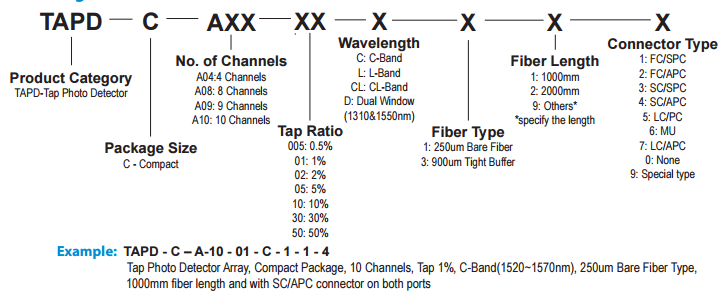
Ordering Information:
 PDF data sheet PDF data sheet
|